Posts

Showing posts from August, 2018

Week 6

Image
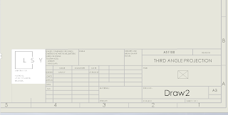
Part 1 Creating drawing template: adding Logo, AS1100, third angle projection into the tittle block. Ps. Later I realised when I view this template in PDF file my logo becomes super blur. After changing the pdf settings (changing high quality lines from 96 to 300) when saving the file fixed this. Part 2 I created this component by using 2 extruded part, first a rectangle with a hole on the right plane and then a 凹 shape at the top plane. I used this method because I thought this would be the most efficient and I will only have 2 features. Using this way my projections looked different than the ones in the brief. So, i place my right plane at the bottom left corner and drag out the other views just so that my drawing would look the same as the brief. Part 3 I created this part by extruding the shape on the front plane, and then extrude cut 2 rectangles from the 2 top faces. Same process of adding texts, showing hidden lines, editing the tittle block.... Part 4...

Week 5

Image
Part 1 I created this stepped shaft by using revolve boss method. Later when I checked my mass on the quiz I realized the mass is incorrect, so I went in and check my model again. One of the dimension is placed over the wrong line and after I fix that the mass is correct. Then I created the same model by extruding each of the cylinders, and then adding fillets. Part 2 Using resolved boss to create a sphere from half a circle Part 3 Using mirror to create a symmetrical shape and then revolve to form the V-grooved pulley. I added the fillets on the larger circle but I dint realize I had to add fillets on the smaller ones as well. When I added those fillets later the mass becomes correct.  part 5 Adding holes onto the beam at 2 directions using linear pattern tool. Part 6 Using a slot and 2 equal circles to create the blade, and then sketching one tooth and using linear pattern tool to create 300 copies of the tooth. Part 7...

Week 4

Image
Part 1 I created this part by adding straight lines to 2 circles and then trimming off part of the circles. Later on when I checked the mass in the quiz I realized my mass is wrong. So I went back to check what is wrong but I couldn't... frustrated. I decided to redo. this time, I used the arc tool and after adding the relations, it worked! Part 2: basically just repeating the same method, just adding "tangent" relations to the lines. No problem! Part 3:  Creating a slot, and adding "equal" relation to the circles to make sure they have the same diameter. Part 4:  Using mirror entities to create wide flange beam by mirroring the sketch about the 2 centerlines. At first I ctrl+clicked all the lines one by one to select them and then I was taught to just drag a window over the lines and TADAAA! everything selected. Part 5: Using "power trim" tool to create this locking disk by trimming off the second circle and ...

Week 3.

Image
First solidworks sketching! Part 1: lines Warming up with drawing a horizontal line from origin using "line" tool, adding dimensions using "Smart Dimension". Part 2: circle Using the circle tool to create circle FROM ORIGIN. Part 3: drawing a part + checking the mass Sketching the part using "Line", adding dimensions and then extrude the part to give thickness. Determining the mass.  Part 4: Editing dimensions Go back into "Sketch" mode and change the dimensions. Part 5: Edit thickness Enter "Edit Feature" to change the thickness. Part 6: Another part+ select materials Same way, new part. Adding dimensions for circles and angles are tricky and frustrating until I figured out how to do it/ asked for help. Selecting materials from hundreds of materials in the list after done extruding the part.  Part 7: And another part. Much quicker process since I've figured out how to add dime...