Posts

Custom mouse design

Image
The idea was a simple, elegant mouse with flowing lines, inspired from hermit crab (middle and top housing being the shell and bottom the creature's body). Some says it looks like mango, or whale...

Keyshot, Conclusion.

Image
Basic tools in keyshot is quite easy to learn. But my OCD kicks in and I took 3 hours on ONE photo just to adjust the lighting so that I get a sleek reflection. My biggest problem: I cant stop until I'm satisfied. Yet to fix this problem. I experimented with different light environments for each photo, need to improve my photography knowledge to understand how camera and lights work. I changed the lens perspective to be more fish eye for the exploded view (to make everything look like they're jumping out) I made an animation of the battery cover, battery and usb come out from the mouse after an orbit scene and I realised that i should make the bottom of the mouse face upwards instead so that its not covered in shadow. But I was halfway through the rendering and there's no time to redo. At least I know next time I can do better. Conclusion for mouse project: Photo rendering and animation are the best parts. I still hate solidworks when things doesn't ...

Mouse Parts and Assembly

Image
1. Middle housing: When I was doing this rib I had problem using cut with surface tool. I created boss extrude and wanted to cut the curve but it failed so I change the boss extrude to surface extrude but it failed as well. So I extrude cut from the middle plane instead and it worked. The middle housing is the first part I did. I was too OCD about putting all features from real mouse onto the model. Later I realized some features are not necessary because it doesn't interact with other parts in the assembly, and also I do not have the time to make my model perfectly accurate. 2. Battery cover After thicken, extruding surface and cut the sides, one face was missing and you can see through the part but this is a solid.... weird. It appears the same when I open the file in other computer as well.  I couldn't fill surface because the boundary is not straight lines and there is a weird curve in the filled surface. I tried offsetting the cut surface in for abo...

Project 2: Logitech Mouse Master Model

Image
Learnt to use features in surfaces, which can be quite hard to use even when following the tutorial videos and step by step pdf file ( projected curve never makes sense to me). Problems I faced throughout the making: 1.  Bottom housing chamfer  In the video it is mentioned that the sketch of the edge of the mouse bottom according to the bottom image can be converted from the sketch from bottom housing but when I did that there is no "chamfer". So I traced the inner edge of the mouse instead of convert entities from the bottom housing chamfer done. 2.Top surface free form. Before the free form my top surface looks like this. I tried adjusting the sketches on middle housing and top surface but I just couldn't achieve the "hill" at the middle front part that is in between the finger dimples so I just jump into free form. my conclusion after playing with free form for hours: its just too hard to control. This is the closest I could ...

Custom bottle

Image
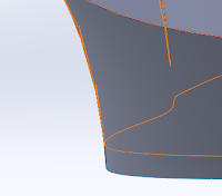
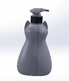
meow! since the instruction was to create ur own custom bottle i took this chance to do a cat shape bottle. What is life without cats? I used loft to create the bottle, just like the dettol pump bottle. but solidworks said guide 1 and section 1 is not intersected or something like that and it couldnt loft. Went to check my drawings (stared at it for 5 mins) until i realise this and fixed it. At first i did the body and ears then i couldnt shell (minimum curvature radius too small) so i roll back to shell the body and leave the ears as solid bodies. Also i realised the reflections on the body looks weird after i mirror the part. Seems like the curve is not connected (the zebra lines are so off) After editting the loft sketches for multiple times i gave up. Im happy with the end results (also no time to keep fixing it)

Other parts

Image
With all the other projects going on I couldnt bother about a lot of details that I normally would, and some of the part sketches are under defined because I thought I will have time to go edit those in the general assembly. Some problems I encounter: 1. too small to see & measure couldnt see what shape it is and couldnt bother to count the numbers... also a lot parts have inner structures not visible from the outside which makes modelling it super frustrating. Life's a lot easier when Katie uploaded drawings with section views (THANKS!) 2. Wrong sub assemblies. made a plunger inner sub assembly and a outer sub assembly just for the plunger assembly because I thought it was just purely to make things stick to each other and I thought that would be more organised. Later realised that the assembly should be put together like how it would assemble together in real life. I quickly redo everything (you remember each single mate when u struggle for 5 ...

Pump bottle

Image
Week 3 bottle modelling. 1. Creating loft: couldn't create loft because there is 2 open loop profiles. For whatever reason Solidworks do not let me choose closed loop even if I open up selection manager.    Somehow I was able to select closed loop after trying for N times, and then closing and reopen solidworks.  2. Swept cut The cut out shape is a bit weird.  Adjusted the sketches and the loft shape for 2 hours to get to a shape that I am happy with.  3. Swept cut the bottom The shape of the cut is not what I expected....  I changed the sketch from a trapezium to a curve.  much better. Mirrored everything, adding neck and threads and fillet.